 Planned Fleet Carriers (1945): Malta, Gibraltar, New Zealand, Africa.
At the same level as the G3 Battlecruisers, B3 and Lion class Battleships, Surrey class cruisers and others, or the CVA-01 for the cold war, the Malta class aircraft carriers remains an interesting what-if the war dragged on post-1946 after Operation Olympic took place. They would remain the largest aircraft carriers planned for the Royal Navy until… the recent Queen Elizabeth class. True 46.900 tons behemoths, twice as big as the 1941 Illustrious, 280 m long and 35.35 m wide, and well armoured, with the largest hangar yet, able to carry and operate 81 aircraft and compared to the Midways.

They were the British equivalents of the Midway class. They were ordered in July 1943, but planning meant they would have been laid down only in the first half of 1945, under the 1945 program. The class comprised four ships, the HMS Malta, Gibraltar, New Zealand and Africa. The first two were planned to be completed in 1947-48. In 1945 however financial consideration made them all cancelled.
They remains an interesting what-if for the cold war, with their tall, open hangar staying useful long-term. A falklands war with two of these deployed, could have put twice as much Harriers and F-4 Phantom in the air, perhaps avoiding more losses to Argentine Aviation.
Development
Conway’s take on the Maltas
This class were ordered in July 1943, but it was not expected that any would be laid down before the first half of 1945. Later, under the 1945 programme it was decided to proceed with Malta and New Zealand for completion in 1950-51, and to defer the other two. The end of the war, and financial considerations, caused all to be cancelled. The design was in between much altered: One of the early projects was for a ship with 5 shafts and an armoured flight deck and hangars, but this was abandoned.
It was eventually decided to depart from previous British practice in the interests of rapid operation of aircraft and to use an open hangar in which engines could be run up. The flight deck of 1-in steel measured 909 ft x 136 ft (277 x 41 m) and there was the usual starboard island and funnel with a second island abaft it to accommodate the larger radar antennae. There were two centreline lifts 54 ft x 46 ft (16.4 x 14 m) and two deck edge ones 56 ft x 35 ft (17 x 11 m), and them, and the two catapults, were designed for aircraft of 30,000 Ib (15 tonnes).
The flight deck, which was 51 ft 10 (15.6 m) in above the deep waterline was not a strength deck, this function being taken by the hangar deck. The hangar area was about 57,000 sq ft (5300 m2) with a clear height of 175 ft (53 m). There were four boiler and four engine rooms divided into two groups with that for the outer shafts forward. The magazines and steering bad box protection, and it had originally been intended that the deck below the hangar deck was to have 6in armour but objections were raised on the grounds that a bomb which hit would be bursting in a confined space, and the armour was raised to the hangar deck except at the sides, probably with some reduction in thickness for stability reasons.
The underwater protection was similar to that in the Eagle class and occupied 21 ft (6.4 m) per side, with expectations of standing a 2,000 Ib (1 ton) charge. The 4.5-in guns of the faster firing Mk V pattern were to be in Mk VII mountings similar to the Mk VI widely used since the war but with a larger 14ft diameter roller path.
Desirable Characteristics

Malta class. scr secret-project, see below
What they could have been ? The design was altered much between 1943 and 1945 as the war progressed and carriers were hard pressed in combat. The 5-propellers solution was considered just to achieve a lower machinery space and maximize hangar space, notably for stability concerns our of a fully armored flight deck and hangars. But practice dictated the rest, and the crews preferred open hangars for fast operation and ventilation. The 900 feet by 136 feet flight deck was dotted by two centerline 54 x 46 feet elevators and two edge lifts 56 x 35 feet, plus the usual 30,000 Ibs-capable catapults shows a margin for future aircraft upgrades and inteoperability with US aircraft as well.
Development Process
A very large protected fleet carrier for 1944
The genesis of the Malta class went back to July 1942, when the Royal Navy formed the Future Building Committee. It chaired by the Deputy First Sea Lord of the time, Admiral Kennedy-Purvis. The goal was to plan the fleet’s requirements until the end of the war, anticipate its readiness and requirements, with set date, January 1944. It was soon concluded that a major expansion of naval aviation was required, notably in light of a return into the Pacific. Which means more aircraft carriers. Albeit there were concerns that large civilain yards and military ones could share the burden of relatively simple, light and inexpansive carriers (The 1942 light carrier program, whic evolved into the Colossus class) the new aircraft planned for the FAA just drove up the size of new fleet carriers.
The combination of size and speed, and of numbers, when comparing the active air group of an Illustrious class, was probably the most desirable characteristic and the bar was set quite high, basically for an armoured carrier with a capacity for 100 aircraft, equivalent of the USN brand new Essex class carriers built for the Pacific. The other elephant in the room was a considerable change in carrier tactics. Instead of many attacks from small aircraft groups, the US model of a “sunday punch”, the use of a large single airstrike was preferred. The main reason was simply the better performances of anti-aircraft guns in general. AA gunners would more easily deal with a limited number of targets rather than be overwhelmed by a swarm of them.
The Full Air Strike Question
Sir Stanley V. Goodall, which was the Director of Naval Construction (DNC) in 1942, proposed several designs with open and closed hangar. On 8 October 1943, the Board of Admiralty selected a closed-hangar design, with an armoured flight deck, five propeller shafts. However early reports of Pacific US carrier operations soon convinced the Board to rework the hangar design. The single airstrike tactis seen above became the new point of focus, dictating the way the hangar space will be done. It was notably concluded than in addition to the aircraft ready to depart on deck, it was necessary to lift up aircraft prepared in the hangar below, engine running and fully loaded, instead of preparing them in deck. 1943 went on, and more reports came from the Pacific.
This means a well-ventilated, open-hangar design. It would notably allow the typical 15-minute engine warm-up to be made in the hangar. The lift themselves would be made faster, as the steam catapult reload system. On 15 May 1944, the Board ordered the DNC to produce an open-hangar design, with deck-edge lifts, as it would allow saving deck space for maximizing the number or aircraft ready to depart. In the end, an unarmoured flight deck was agreed upon due to stability concerns, in June 1942, by the Controller of the Navy, Admiral Wake-Walker. It was approved by the Fifth Sea Lord Admiral Boyd.
The new design called “X” was setup for a lenght of 900 ft (270 m) at the waterline, which was already massive (no ship of that size ever was built in Britain, apart transatlantic liners), was submitted to the Board on 10 August. It was however not approved. By October reports adressed concerns that such a size meant the carrier might have problems manoeuvring, notably in constricted harbours. The DNC thus was asked for two smaller designs designated X1, which was 50 ft (15 m) shorter, and Y, which was 150 ft (46 m) shorter. Design Y however proved too short for the larger aircraft anticipated. That left only the first option, approved by the then First Sea Lord Admiral Cunningham. X1 was submitted to the Board on 12 April 1945, fully worked out for a planned final approval. But that late into the war, it just never came. The Board minutes states for the 31 August 1945, 15 days after the Japanese surrender, that “further consideration of the design had been postponed”. This made the Malta class, a superb what-if for historians to consider.
Design of the class

Design by IA Sturton, for Warship International, 1971, #3. src full plans
Hull and general design
The Malta class on paper were quite formidable. They were way larger in tonnage and size than the 1942 Essex class, the bedrock of the 1943-45 island hopping campaign of the USN, and looked towards a later project, the first US armoured carriers, and largest to date, the Midway class. But they were in the end, two very different animals. The Malta class, X1 design as approved, was 897 feet (273.4 m) in length overall, 850 feet (259.1 m) at the waterline. The Midways were much lower, but longer at 295 m overall, and larger at deck level, at 41.25 versus 115 feet 6 inches or 35.2 m at the waterline, likely around 39-40 meters at deck level. The draught was heavier at 35 feet (10.7 m), deeply loaded versus 33 ft (10 m). Final displacement was calculated at 46,890 long tons (47,642 t) under standard load, 57,700 long tons (58,626 t) under deep load. The Midway were 45,000 long tons/60,000 long tons, so very comparable.
The Malta class metacentric height, due to the choice of a double hangar, was estimated to be 8.42 feet (2.6 m) under standard load, 12.8 feet (3.9 m) under deep load.


The general outlook showed a “stretched up” Indefatigable, but instead of taller double protected hangars, had a single, unarmoured hangar to accept future larger aircraft, with a large height clearance. As common practice since the 1930s Ark Royal design, the flight deck lip forward was fused and integrated without separation with the stem, unlike US carriers which separared the prow and deck above. This was a way to withstand harsh North Atlantic conditions, and the USN will learn how much it counted, seeing the damage caused in 1945 by Typhoon Cobra.

Malta, cutaway and deck. src: Ytube Drachinifel video, see below
Otherwise, the ship had a large island, perhaps larger in proportion to earlier designs, and taller due to the general up-scaling of the design, six deck tall, with a fire control tower for the on board artillery, a tripod mast to carry sensors, a lattice mast aft to carry the largest air search radar planned yet, and in between a large, single funnel. Further fire control towers were located aft of the island, in order to manage both the main artillery and light AA. The crew was also gigantic, with 3,520 officers and other ranks required just to man the ship, Conways adding a total of 3,535 as a high estimate presumably with the air crew, and 2,780 low estimate.
One interesting perk about the island: The unarmoured flight deck required an expansion amidships, so the island could not be a single structure, and was split to reduce turbulence around the islands. These two section were of unequal size (largest forward) with the single funnel forward. The very shape of this separation, like a wing, allowed the wind to pass through and reduce turbulence around, as well as providing more space for radars and fire-controls. This was the largest island ever planned for any allied aircraft carrier. The Midway class had a much more compact structure around a very large funnel. On that plan, the Midway boasted 212,000 hp for 33 knots, the Pacific fast carrier standard. How the Malta compares ?
Powerplant
The Malta class were not equal in power, but took advantage a shorter hull (as far as waterline was concerned). They would need an ungodly amount of power, still, superior even to the Vanguard in construction, but sticking to the classic soltion of four, instead of five shaft in an effort to reduce height. They were planned to use four Parsons double-reduction geared steam turbines, driving each their own shaft. Steam came from eight Admiralty 3-drum boilers, distributed among four boiler compartments, in two groups of two amidship. However, all four turbines were in a single compartment further aft. So ASW protection around was well cared about.
These turbines could produce 50,000 shp each, for a grand total of 200,000 shp (150,000 kW), for a planned 33.25 knots (61.58 km/h; 38.26 mph), same as the Midways. The roomy hull also allowed to carry 7,000 long tons (7,112 t) of fuel oil as well as large amounts of diesel fuel to power emergency generators. The range was planned to be 7,100 nautical miles (13,100 km; 8,200 mi) at 20 knots (37 km/h; 23 mph), or 5,600 nautical miles (10,400 km; 6,400 mi) at 24 knots (44 km/h; 28 mph), compatible with Pacific Operations. To compare, this was 20,000 nmi at 15 knots for the Midways. We can presume thus c12-15,000 nm at 15 knots, but it’s only conjectural. So yes, the Malta class were “short-legged” in comparison.
Protection
The final protection included a less well-protected flight deck, but the hangar deck took the bulk of the protection, to use a sandwich effect and reduce the top-heavy characteristics. The four-inch (102 mm) thick hangar-deck armour was reduced compared to the 6 in (150 mm) from the earlier X design. The waterline armour belt was the same as the artillery at 4 inches thick, but just on a limited amidship central section, roughly 1/3 of the total lenght of the ship. It still formed an armoured citadel, closed by three-inch (76 mm) transverse bulkheads fore and aft.
There was also a stray of 1/2 inch or 38 mm armour, 40 feet (12.2 m) forward, 60 feet (18.3 m) aft of it to protect the waterline, only against splinter damage. To compare the US Midway class were not “fully armoured” and only had 1-1/2 inches STS (flight deck), 1 inch (bulkheads & subdivisions), then 2-1/2 inches for the hangar floor, 1-1/2 inches for the citadel roof (armoured deck below), but 4 inches bulkheads). The Malta class magazines were protected like the steering gear, both outside the armoured citadel. The Magazines had 4-inch (100 mm) roofs and sides, and 3-inch ends (magazines), but the steering gear had 3-inch sides and ends.
For ASW protection, al four boiler rooms were separated as said above, with extra protection and still a protection between turbines. Both magazines and steering were boxed with armour. Compartmentation was similar to the Eagle class. To buffer torpedo damage, there was a layered system comprising liquid and air-filled compartments. They were themselves backed by an inclined holding bulkhead, 4 inches (100) thick at the top, then tapered down to 2 inches (51 mm) at the bottom. Calculations were for a 1,200-pound (540 kg) explosive charge. As a remainder a Japanese Long lance carried a 490 kg (1080 lb) warhead, so there was some margin. The earlier design was even more almbitious, calculated to resist a 2,000-pound (910 kg) charge,, but not a 1,000-pound (450 kg) charge. To prove this, there was a full-scale test.
Fire was a real concern also, especially after 1944 experience in the Pacific, with seawater pumped into gasoline lines when empty and other measures. In case of fire, the hangar, opened outside and ventilated, was intended to be divided by four sliding steel doors instead of curtains as in US practice. They would have been equipped also with several fire fighting posts along it, likely five, as defined by these doors, and a copious amount of portable fire extinguishers and fire hoses points using pumped up seawater.
Armament
The Armament was also the same as the Eagle class, repeating also partly earlier designs, but with the MkVI dual purpose gun models. The Malta class presented a battery of sixteen QF 4.5-inch (113 mm) Mark VII dual-purpose guns in eight powered RP 41 Mk VII twin-gun turrets placed the usual way as previous carriers, on sponson cutouts in the deck fore and aft, two pairs forward, tgo aft, with the same low-roof turret to stay below the deck line. The light anti-aircraft (AA) armament varied, but comprised in its final form some fifty-five 40 mm Bofors AA guns, in eight sextuple mounts. These were the new, stabilised and powered RP 50 Mk VI mounts planned for the late war generation of cruisers and battleships as well. This was completed by seven single mounts, also likely Bofors.
4.5 in/45 QF Mk V

The 4.5-inch gun had a maximum range of 20,760 yd (18,980 m) at an elevation of +45° and a ceiling of 41,000 ft (12,000 m). Position is the one decribed above. They could be used for anti-ship defensive fire as well. For more data see navweaps.
Bofors Mk X, Mk. III
Bofors gun had a maximum range of 10,750 yd (9,830 m) and a ceiling of 23,500 ft (7,200 m). Drawings shows the location of three mounts on the starboard side, two aft on outer sponsons close to the landing deck lip, two in a sponsoned deck structure covering the aft angle, then two visible on sponsons on the starboard side, one amidship, one aft of the forward main turret pair. One was located on the port side deck, in front the the island. Another was located behind the funnel on the island’s roof.
Sensors
By August 1944 a study planned for a new model of heavier early warning radars and height-finders, with four surface search radars, eight gunnery and fire-control radars. Historian David Hobbs reports Type 960 early warning, Type 982 intercept, Type 983 height-finding and Type 293M target indication radars. Additional gunnery radars would be fitted on the sextuple Bofors mounts.
Air Facilities

Hangar Comparisons src
The flight deck was a reflection of earlier designs, and had limited overhangs and sponsons. For maximizing air operations, four deck lifts were installed, two on the centerline, one just aft of the catapults and one at the rear, placed in a way a mass-flight, unassisted could be done from there, with more aircraft coming up. The two side lifts were also placed aft for the same reasons, in order to bring three aircraft at once and accelerate the pace. The landing area was the largest designed so far, made for 20,000 lb (9.1 t) aircraft at 75 kn (139 km/h; 86 mph) if needed, with 16 arrestor cables to stop them, backed up by three crash barricades preventing them to crashing into parked aircraft forward, adopted from US practice.
The forward hydraulic aircraft catapults were of a brand new model, to launch fully laden aircraft at 130 knots (240 km/h; 150 mph), up to 14 tonnes. The four 30,000-pound (14,000 kg) capacity lifts comprised centerline ones at 45 by 46 ft (13.7 by 14 m) and deck edge ones at 54 by 36 ft (16.5 by 11m), portside. They were much faster lift with gravity-braked return. The hangar measured 440 ft (134.1 m) long, 90 ft (27.4 m) in width, so not as long as the entire hull, albeit smaller spaces were made available as workshops, or limited capacity. The eight was generous at 17 ft 6 in (5.33 m), to US standards, likely able to support spare parts under the roof. So by adding the deck and hangar areas estimates were between 80 and 108 aircraft depending on the types of suadrons carried. This was less than a Midway class, but a bit more than an Implacable class. Total avgas storage represented however a staggering 190,000 imp gal (860,000 L).
Air Group
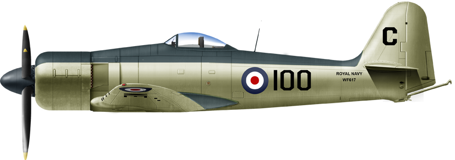
Hawker Sea Fury
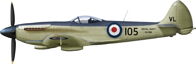
Seafire F.17
Firefly F.1

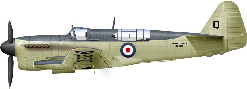
Blackburn Firebrand TF MK.IV
That matter is still the object of debates. In 1944 the “ready air group” would have comprised a mix or alternative of Seafire, Firefly, Sea Hornet, Sea Fury as fighters, and Barracuda as well as Firebrand torpedo bombers. The latter was likely the one to be adopted as main type, as the Barracudas were the object of much criticism. Progresses had been made on the seafire, and the landing gear notably was a bit more resistant, but still short-legged. As showed Korean war operations, it is clear that the heavier, but more more rugged Sea Fury (1945) would have been preferred s a standard. The Sea Hornet was usable to escort torpedo-bombers thanks to their range, and the older Firefly was still extremely valuable as a versatile attack aircraft. So a 1946 air group would have been likely two squadrons of Sea Furies, one optional of seafires (for the local CAP), one of Sea Hornets, one of Firebrand and one or two of Fireflies of the late type, so 5-6 squadrons of 12 each, making for 72 aircraft as a baseline, one more optional squadron and spare aircraft (not precised).
⚙ specifications X1 design |
|
| Displacement | 46,890 long tons (47,642 t) standard, 57,700 long tons (58,626 t) deep load |
| Dimensions | 897 ft x 115 ft 6 in x 35 ft (273.4 x 35.2 x 10.7 m) |
| Propulsion | 4 shafts steam turbines, 8 Admiralty 3-drum boilers: 200,000 shp (150,000 kW) |
| Speed | 33.25 knots (61.58 km/h; 38.26 mph) |
| Range | 7,100 nmi (13,100 km; 8,200 mi) at 20 knots (37 km/h; 23 mph) |
| Armament | 8×2 QF 4.5-in DP, 8×7 40 mm Bofors |
| Protection | Belt 4 in, deck 4 in, bulkheads 2–4 in |
| Sensors | Likely similar to the planned Eagle class |
| Air Group | 2 catapults, 2 lifts, 2 hangars, 80–108 aircraft |
| Crew | 2780 to 3535 |
Construction: The Malta class
The four ships were ordered in July 1943 but Africa; originally ordered as an unnamed Audacious-class carrier, was modified to a Malta-class to round the class to four, on 12 July 1943, so three days before the official order for Malta, New Zealand and Gibraltar. New Zealand was originally ordered from Cammell Laird, but the contract was transferred to Harland and Wolff, on 22 July 1944, so about a year later. Still no keel was laid down, no material piled up. The Admiralty ordered Vickers indeed not to do so by 27 April 1944. The final drawings were indeed never issued to the builders as the design kept changing. What’s remaining up to debate of any preliminary work has been done. None of the ships was ever laid down, all cancelled either in October or December 1945, with some sources stating January 1946.
 HMS Malta
Malta was ordered under yard number 624 from John Brown, Clydebank on 15 July 1943. No official order was confirmed and she was cancelled in January 1946 or 13 December 1945 depending on the sources.
HMS Gibraltar
Gibraltar was ordered under yard number 82 from Vickers-Armstrong, Tyne on 15 July 1943. No official order was confirmed and she was cancelled on 15 October 1945.
HMS New Zealand
New Zealand was planned ordered under yard number 1304 from Harland & Wolff, Belfast on 15 July 1943. No official order was confirmed and she was cancelled in January 1946 or 13 December 1945 depending on the sources.
HMS Africa
Africa was planned ordered under yard number 722 from Fairfield, Govan on 15 July 1943. No official order was confirmed and she was cancelled on 15 October 1945.
Read More/Src
Books
Brown, David K. (2006). Nelson to Vanguard: Warship Design and Development 1923–1945. Chatham
Campbell, John (1985). Naval Weapons of World War II. Annapolis NIP
Chesneau, Roger (1995). Aircraft Carriers of the World, 1914 to the Present: An Illustrated Encyclopedia NIP
Chesneau, Roger, ed. (1980). Conway’s All the World’s Fighting Ships 1922–1946. Conway Maritime Press.
Friedman, Norman (1988). British Carrier Aviation: The Evolution of the Ships and Their Aircraft. NIP
Hobbs, David (2013). British Aircraft Carriers: Design, Development and Service Histories. Seaforth Publishing.
Links
globalsecurity.org
warhistory.org
Ships Cover for Malta class aircraft carriers (cancelled) Greenwhich Mus.
secretprojects.co.uk
navygeneralboard.com
Malta-class_aircraft_carrier
navypedia.org
xoomer.virgilio.it
stefsap.wordpress.com: Warship International, 1971, #3.
truevaluemetrics.org
armouredcarriers.com
alternateuniversewarships.com
combinedfleet.com malta class uchronia
Videos
Video by Drachinifel
See also the one by Dr. Alex.
Kits
Imperial Hobby Productions (IHP) 1:700