 United Kingdom (1921): 4 ships ordered 1921, cancelled 1922.
The G3 class Battlecruiser were a project launched in 1920 and approved in 1921 but later cancelled due to the Washington Treaty. Displacing more than 55,000 tonnes fully loaded with a battery of nine 16-inches guns and a dual purpose and AA battery ahead of its time, as well as an unprecedented output of 160,000 hp for 32 knots, plus an all-or nothing armour scheme, these ships were among the most ambitious Britain ever planned. Nearly laid down at John Brown, construction was suspended on 11 November 1921, due to the start of the Washington Treaty negociations and they were cancelled on 21 February 1922, all four unnamed. Many aspects later ended on the next Nelson class battleships.
Development
1916 Concerns
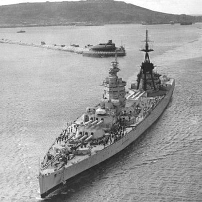
 In 1916, after the battle of Jutland, lessons had been incorporated into new designs, notably the ones already in construction, like the “admiral class” of which a single ship was completed, HMS Hood. After the two earlier Renown class and Fisher’s fantasy “baltic cruiser” of the Furious class, they became the most formidable of their type to be built in WWI. However the same year, that summer of 1916 the lessons of jutland led the admiralty to completely reconsider the design of the “Admirals” leading to a cancellation of the class, and completion, much delayed, of Hood on a modified design. The admiralty also looked at the 1916 United States Congress authorization of a large number of battleships and battlecruisers to create a navy “second to none”.
In 1917, the Japanese launched a very large program of their own, with the Amagi class approved as part of the “Eight-eight” program. So it was believed that Britain would lage behind both in numbers and quality of battlecruisers. As the war was still going on, it was learned about German construction of new 30,000t battlecruisers, the Mackensen class, for the first time armed with 35 cm (13.8 inch) instead of the usual 28 cm and said capable of 28 kts. Their armour details were unknown but after jutland it was suspected their protection as better overall. Seven ships already were ordered in 1915 (the latter became the modified Esatz Yorck class), so this was also an immediate concern.
All this bubbling up into a new design urgently, as no “new” capital ship was ordered after Jutland. The three Furious were deemed impractical and were converted as aircraft carriers, and the two Renown were in fact two “improved Revenge” ordered as emergency builds. So with the cancellation of the Admiral class, and loss of most of the Lion class and older battlecruisers (apart Tiger), it was time to look at a fresh new design, almost starting from a blank page.
Pre-Washington Plans
Before the momentous Washington conference, so in a gap between the end of the war and signing of the treaty in 1922 there was a gap in which the “three great” navies of the time, later concerned by the 5:5:3 ratio limits, were engaged in a race for the largest capital ships, battleships as well as battlecruisers. The US worked on the massive South Dakota and Lexington class (the last already well advanced and capable of 32 knots) and the Japanese, on the Tosa and Amagi class respectively, as an answer. This left the Royal Navy to plan its own N3 (battleships) and G3 (Battlecruisers) classes. The names were derived from admiralty plans proposal identifiers, as in reality the “G3” started with letters of the alphabet running backwards from K to G while battleship designs under consideration had design letters from L upwards, so in reverse.
One element fed the new design, the aftermath of the scuttling of the Horchseeflotte at Scapa Flow on 21 June 1919. This suddenly gave access to British engineers of many German battleships and battlecruiser design, with in particular SMS Hindenburg being examined but even more the battleship Baden, still preserved in shallow waters and accessible unlike others. The British led an investigaton to gather design details, in particular of the armour scheme, giving a serious input of German protection technology that infused consideration for the design scheme of the future ships. The initial requirement was for four battlecruisers capped to 53,100 long tons (54,000 t) to use British dockyards and the Suez Canal.
The K series
‘K2’ and ‘K3’, had a general layout very close to HMS Hood, but were armed with very large guns 18-inch (457mm) guns, alread developed for the previous “light battlecruiser” Furious design, in either four twin, or three triple gun turrets. The numeral came from the number of guns in each turret. Displacement rose to the maximum possible at 52,000-53,100 long tons (52,800-54,000 t) and top speed was limited to 30 knots (56 km/h; 35 mph). Given their size, they could only dock in an ex-German floating dock and or the Gladstone Dock of Liverpool.
The J series
Only one entry, ‘J3’ was 10,000 long tons (10,000 t) less, by reducing the main armament to nine good old and trusted 15-in/50 (381 mm) guns (still formidable) wit the main deck armour decreased slightly to 4 in (102 mm). This allowed them to dock anywhere as Hood could dock and was compatible with Suez and Panama. But the caliber was judged insuficient and the admiralty wanted 18-in guns for uniformity with the battleships.
The I series
‘I3’ was another single variant, also saving weight, but concentrating the main armament amidships, with ‘X’ turret between the forward superstructure and funnels. However additional hull and machinery weights made the displacement rose to just below ‘K3’. It still could be docked in Rosyth and Portsmouth and go through both both canals (albeit the Suez Canal needed to be deepened). The main armament however had a blind spot aft of 40°.
The H series
The ‘H3’ explored a reduction in turrets numbers, but with 18-in guns:
-‘H3a’ both turrets forward of the superstructure.
-‘H3b’ one forward, the other aft of the forward superstructure, 45,000 long tons (46,000 t).
-‘H3c’ same as above but turrets lowever by one deck, saving 1,250 long tons (1,270 t).
For all: maximum speed 33 knots (61 km/h; 38 mph).
The G series
The admiralty disliked this reduction of firepower, and thus the ‘G3’ was proposed with three triple turrets, but a compromise was found, down to 16.5-inch (419 mm) guns instead of 18-inches to save weight. This last variant was accepted by December 1920. Still, changes were made when plans were finalized in early 1921. The machinery space needed reduction and thus, the powerplant was downgraded from 180,000 to 160,000 hp, the main armament was reduced from 16.5 in to 16 in (406 mm). By the way, the new 16.5 inches guns were an interesting case, the final guns were finally used on the Nelson class battleships (see below).
Design of the class
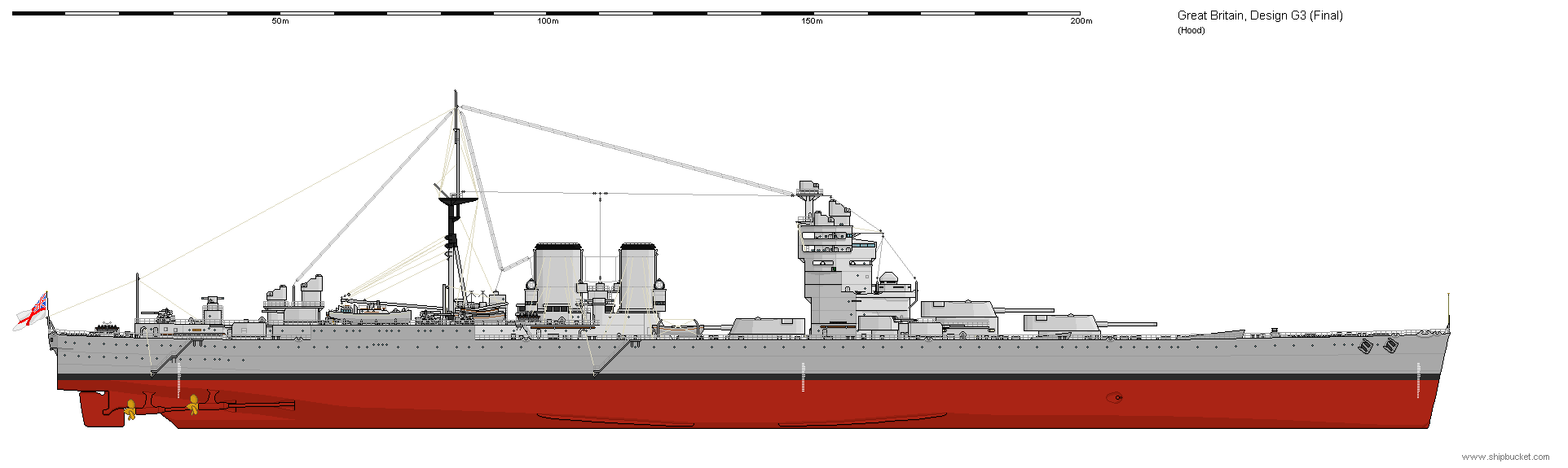
The G3s were still very much in te streight line of dreadnoughts and their British designs, with the the concentration of the main battery forward of the bridge and engineering spaces. This resulted in the same tanker-like appearance that was criticized on the Nelsons. Existing dockyard facilities, was a requirement that constrained the artillery management and layout so that their length was moderate, and this plays as well in trh final weight of armour coverig a reduced lenght. These solution proved very popular and percolated in latter fast battleships designs. The French took this idea to an extreme by having their armour concentrated aorund a forward quad turret arrangement, but the three turrets close together, albeit “X” was separated from “A-B” forward and had a less interesting fire arc. This loss of heavy fire astern was justifiable at the time when firing broadside was still the norm in 1921. This started to shift later, with a new emphasis over “crossing the T” tactics.
Hull and general design

The G3 class had an overall length of 856 feet (260.9 m), beam of 106 feet (32.3 m), draught of 36 feet (11.0 m) (deeply loaded) for a “moderate” displacement of 48,400 long tons (49,200 t) at normal load, 53,909 long tons (54,774 t) deep load. This was still a jump of over 8,000 long tons (8,100 t) compared to the admiral class, and for comparison, the not so distant Lion class was “just” 26,270 long tons (26,690 t) at normal load, so that was a 45% increase.
Their metacentric height was 7.786 feet (2.4 m) at deep load and they sported a complete double bottom. Other protection particulars aer shown below. A common trait of G3 and N3 designs was their tower bridge structure behind the first two gun turrets. It ended on the Nelson class design, a,d was soon nicknamed the “queen ann’s mansion” to its wedge like shape, but it was discovered later acting as a sail in high wind, distrupting the ship’s ability to manoeuver at low speed. However instead of the classic tripod masts with stacked platforms, this looked “clean” and provided a better and more stable foundation for fire-control. It also greatly improved accommodation and offered better protection from the weather, in a word, it looked lean and clean, modern. Later variation of that bridge structure ended on the rebuilt Queen Elizabeth class as well as the rebuilt Renown and the King Gorge V class, albeit in extended variants.
Other than that, the G3 class also shared many other similarities with the N3s, and past this artillery concentration around the bridge, the remainder of the ship showed a large structure, partly meeting the hull aft, starting with a wedge-shaped forward section to offer as much as free arc aft to “X” turret, but still leaving the 40° astern blind spot as said above. There was jus no way to fit all the remaining structures behind the bridge without adding extra lenght and weight to the citadel. Hence armour was tapered down significantly past “X” turret.
The aft structure extended for almost 50% of the lenght, with two funnels of unequal size given the way the exhausts were truncated and a clear separation of machinery space, all aft and well extended. Pas the two funnels a tripod mainmast was installed for utility, as it supported a boom crane servicing all the boats stacked on the deck of this structure. Past these, a small structure supported three fire control towers (two in line on the bridge’s roof forward). The secondary armment position was unclear in the first design, only showing the location of the main artillery and protection layout.

Scale 1:192. Plan shows the profile, half deck and section plans, illustrating the proposed armour and protection arrangement for the G3 class battlecruiser. The title of the plan is “1921-22 Capital Ships”. An Admiralty Minute Board stamp, dated 12 August 1921 is printed on the drawing. The plan bears the signature of Sir Eustace Tennyson d’Eyncourt [Director of Naval Construction 1912-1924].
Powerplant
These battlecruisers needed originally to reach 32-33 knots, so the machinery was “garagantuan” even compared to the Hood class. TheY would have had four geared steam turbine sets corresponding to four shaft propellers. They had also a single rudder and the propellers and struts arranengement were classic. No innovation there. The turbines were separated between two HP turbines (outer ones) rated for 58,0000 hp or 116,000 hp total for speed, and two LP inner turbines for cruising, rated 22,000 hp each or 44,000 total. The HP turbines would have been the largest Parsons turbines ever produced, larger than those of the N3 class.
The cruise turbines were however essentially the same models as on the N3 for scale economies. Arranged was however in three engine rooms, with two outer turbines in the forward one (wing shafts) and middle one with the port inner shaft, aft engine room for the starboard inner shaft turbine. The outer machinery spaces needed to be flooded before the central one was reached, so this became the backup machinery. They were powered by no less than twenty Yarrow small-tube boilers, divided between nine boiler rooms. Total output was an unpredented 160,000 shaft horsepower (120,000 kW). But this wa smore realistic than 180,000 hp, that required 24 boilers or more.
These twenty Yarrow Boilers, same as on the N3 class, worked at a pressure of 200 psi (1,379 kPa), temperature of 392 °F (200 °C), using superheating with extra oil sprinklers and turbo pumps to massively increase air intake. Top speed was on paper 32 knots (59 km/h; 37 mph), quite honourable. To compare the Admiral class was similarly fast but in 1920. After modifications in 1941 it fell to 30 kts and that would be the case likely for the G3 if built and modified in the interwar. By comparison the N3 battleships had only two sets for 20 boilers resulting in only 56,000 shp (42,000 kW) and thus, 23 knots. The G3 had almost thice the output and so were the most powerful British capital ships ever planned, as the KG V class fast battleships “only” were rated for 110,000 shp (82,000 kW).
The ships had a maximum capacity of 5,000 long tons (5,100 t), all fuel oil since the 1912 Queen Elizabeth class. The 22,000-shaft-horsepower (16,000 kW) cruising turbines were used in that for a maximum range of 7,000 nautical miles (13,000 km; 8,100 mi) at 16 knots (30 km/h; 18 mph). In addition, the ships had an auxiliary power, six turbo-driven 250-kilowatt (335 hp) dynamos, and two 300-kilowatt (402 hp) diesel generators to power all systems when the machinery was cold.
Protection
It was downgraded compared to the N3 design, which had to equate their large caliber guns with similar protection. Given their battlecruiser nature, the G3 had a lighter armour scheme, but they innovated with for the first tile an “all or nothing” protection scheme. Medium thickness was useless against heavy-calibre as shown at Jutland and other clashes, so the vitals were all protected with thickest armour, the rest unarmoured. This was a US battleship design trend started by the Nevada class. Nevertheless in the British case, that would have resulted in a very short, and thus not buoyant enough citadel. This reserve buoyancy was like a guarantee to keep the ship stable in battle. So it was lenghtened to the aft setion to protect the machinery space and integrated an aft bulkhead far aft of “X” turret. Here are the details:
Waterline belt
Maximum thickness 14 inches (356 mm), 522 feet (159.1 m) long from the forward edge of “A” barbette to the aft 6-in magazine. The top of the armour was angled at 18° outwards to redirect for plunging fire. This angle increased artificially also the relative thickness in horizontal fire. There was still the risk of shellfire going over or under it. The belt height was 14 feet 3 inches (4.3 m) total, inc. 4 feet 6 inches (1.4 m) below waterline. It was tapered down over 259 feet (78.9 m) foward to 12 inches (305 mm).
Its lower edge abreast the magazines went down to 3 feet (0.9 m) for a 4 inches (100 mm) thickness in high-tensile steel at 36°. It was to prevent penetration in the magazines via a wave trough at high speed. It was extended forward 46 feet (14.0 m) tapared down to 6 inches and then 2.25 inches (57 mm) in two steps.
Main Bulkheads
The forward and rear belt were closed by 12-inch fwd. and 10-inch (254 mm) aft transverse bulkheads.
Machinery Armour
The funnel and boiler room ventilation shafts had armoured boxes 116 feet (35.4 m) long to prevent shells from behind to enter ‘X’ magazine. These narrowed to 21° and 12 inches nearest to the magazine. Then they tapered down in steps to 9 inches (229 mm), 6 inches, 5 inches (127 mm) and 4 inches (102 mm).
Armoured deck

From Greenwhich Museum
It matched the waterline belt in lenght and sloped on both sides down 2.5° to meet its upper edge. Maximum thickness was 8 inches (203 mm) from “A” barbette over the mid-boiler rooms, then was down to 4 inches over the rear engine/boiler rooms. However it increased to 7 inches (180 mm) over the rear engine room when covering the aft 6-inch magazines. It extended forward some 46 feet over the torpedo compartment at 8 inches, then 6 inches. After, this deck was reduced over 106 feet 9 inches (32.5 m) long to 5 inches thick and then further tapered down over 27 feet 4 inches (8.3 m) to 3 inches (76 mm) when meeting the stern.
Turrets
These were large turrets to accomodate the new guns, of a shape that resembled that of the next Nelson class. Sloped forward and on the sides were moderate but the forward face was well rounded, and composed of cast elements, reaching 17.5 inches (444 mm). The sides started at 13 inches (330 mm) but down to 10 inches (229mm). The roof was 8-inches thick, moslty thought to “bounce off” incoming rounds in relative plunging fire.
Barbettes
They ranged from 11 to 14 inches (279 to 356 mm) in thickness, with the heaviest part over the deck and down until meeting the citadel and armour deck. It was carefully arranged to minimize any penetration risk. The 11 inches armour was maintained below the armour deck, down to the ammunition rooms.
Conning tower
Installed forward of the bridge it was high enough to clear out the roofline of “B” turret. This tower had cast walls ranging from 9 to 12 inches thick forward, then thinner aft, with a long communications tube 8 inches thick down to the armour deck. The fire-control director atop the conning tower also was protected by an armoured hood 3-5 inches thick.
Anti-torpedo bulges
In addition to the double bottom 5–7 feet (1.5–2.1 m) in depth, there were generous anti-torpedo bulges, capable of defeating a 750-pound (340 kg) torpedo warhead. The scheme comprised an outer air space, inner buoyancy space followed by the proper armoured bulkhead in two layers of 0.875-inch (22 mm) in high-tensile steel. It was 13.5 feet (4.1 m) inboard from the side. Next were the ammunition magazine and machinery spaces. Postwar tests on a scaled down model replica showed it was better filling the buoyancy space with water rather than sealed steel crushing tubes (Hood’s protection). It was just as effective and weighed less. There was acompressed air system to blow the water out in case the ship, hit and flooding after 2 torpedo hits, needed to be retored upright.
Armament
These ships emphazised high muzzle velocity, with a relatively lighter shell, as per German practice, instead of the classic BL 15-inch Mark I gun/42, lower-muzzle-velocity but with heavy shells. The rest of the armament was really modern as they lacked a classic secondary casemated battery, and instead focused on a new generation of twin turrets, a brand new concept for that caliber, with twin mounts. The pompom rounds the AA protection, and these were “classic” and dependable guns with a high rate of fire, essentially scaled-up Maxim machine guns. Like the future Nelson, the G3 also looked at an impressive torpedo battery with the new and rare, massive 24.5-inch (620 mm) models later also found on the Nelsons. The core idea was to create a useful “battleship torpedo”, for broadside engagements, taking in account longer ranges and better payloads.
BL 16-inch MK.1
 The BL 16-inch MK.1 was ordered and started construction before the cancellation of the ship, later to be sheared down and repurposed for the Nelson class Battleships. Their predecessors, the 16.5 inches Mark I (419 mm) were never completed. The BL 16-inch Mark I were 45-calibre guns located in three triple hydraulically powered Mark I gun turrets as seen above, ‘A’ and ‘B’ were in superfiring positions forward, ‘X’ aft of the bridge, forward amidships. Specs:
They fired 2,048-pound (929 kg) shells at 2,670 ft/s (810 m/s).
They could be depress to −3°, elevated to 40°.
Maximum range was 38,000 yards (35,000 m) at the above
Maximum stowage was 116 shells per gun.
For more, see the Mark 2 on navweaps and data on the Nelson class.
6-inch Mark XXII
 The design was significantly ahead of its time using even an exemplary AA complement, with this dual purpose secondary armament of sixteen BL 6-inch Mark XXII guns. They were located in superfiring twin turrets instead of casemates or shields and sited around the forward superstructure with four at the stern. The forward turrets had 150 rounds per gun, the rear ones 110 rounds per gun. They were dual purpose as they could elevate from –5° to +60° and fire 100-pound (45 kg) HE shells at a muzzle velocity of 2,945 ft/s (898 m/s). The shells could be setup for a time fuse to explose in the air at a setup altitude. Maximum range was 25,800 yd (23,600 m) at 45° elevation for a rate of fire of five rounds per minute. That system eventually landed on Nelson and Rodney.
Specs:
Gun Length oa: 309.7 in (7.866 m), Bore Length: 300 in (7.620 m), Rifling Length: 255.6 in (6.491 m)
Grooves: 36, 0.046 in deep x 0.3759 (1.17 x 9.548 mm), Lands: 0.1477 in (3.752 mm), twist: Uniform RH 1 in 30.
Chamber Volume: 1,750 in3 (28.7 dm3)
Rate Of Fire: 5 rounds per minute at a muzzle Velocity of 2,945 fps (898 mps)
Range/elevation: 22.9°: 20,000 yards (18,290 m), 45°: 25,800 yards (23,590 m).
2-pdr (40 mm (1.6 in)) pompom
Probably the first iteration of this sytem oa British capital ship, they were present in four octuple barrels, so 32 total, as per the QF 2-pounder naval gun lineage. If the ships had been approved in 1921 and completed in 1924, that means the QF 2-pounder Mark VIII would have been likely adopted as its development started in 1923. This ended as a bedrock of British ships. Indeed the previous QF 1-pounder Mark II (ordered 1915) was a single-mount only gun. There were two abaft the funnels and two at the stern, provided with 1300 rounds of ammunition each.
Specs:
Calibre: 40 mm L/39
Shell Weight: 2 lb (910 g) round
Rate of Fire: 115 rpm fully automatic
Effective Range: 3,800 yards (3,475 m).
Muzzle Velocity: 1,920 ft/s (590 m/s).
Torpedoes
The G3 class battelcruisers had two submerged, broadside-firing torpedo tubes in a compartment just forward of the ‘A’ ammunition room, but on the platform deck. Each tube ahad a reserve of six 24.5-inch (620 mm) torpedoes in peacetime, eight in wartime. These Mark I torpedoes would bring a massive, 743 pounds (337 kg) TNT warhead thanks to an oxygen-enriched air powerplant, through two speed settings 15,000 yards (13,716 m) at 35 knots (65 km/h; 40 mph), or 20,000 yards (18,288 m) at 30 knots (56 km/h; 35 mph). For more, see the Nelson class as well, as they inherited these.
Fire Control
The main guns could be controlled from any of the three director-control towers (DCT) forward, as primary FCS, mounted on top of the forward superstructure one on the conning tower roof in an armoured hood, another on the bridge’s roof same, and a third aft. All three had a 41-foot (12.5 m) coincidence rangefinder in an armoured housing. The secondary armament was also controlled by three DCTs, two on either side of the main roof DCR on the bridge and a third aft. The anti-aircraft guns were controlled by a high-angle control system mounted on top of the forward superstructure, dominating all the others. Each pom-pom mount also had its own director. There was an extra height-finder aft. There were also two 15-foot (4.6 m) torpedo rangefinders, located on the sides of the funnels.
Air Group
Albeit this was never planned, we can estimates that somehing would have been planned for an hypothetical completion in 1924. If the ships could be fitted with a catapult on the roof of either “B” or “X” turret, it could have accomodated a Supermarine seagull (1921). The main issue was the presence of a crane, derrick type, or boom type to recover it. The issue was the storage of spare seaplanes, so it a boom crane was fitted at the rear of the bridge to serve “X” turret the most likely place was either side of the bridge on deck. But in any case, they would be likely destroyed by the blast if “X” fired forwards. So likely a single one was to be stored on catapult and launched for artillery spotting before the guns were put to use. The blast damage was likely to also rock the mechanisms on the catapult as shown by Rodney having one only from 1936, on “X”. Before that, the seagull was loctaed behind the bridge, far from blast damage, but this was not ideal.

⚙ specifications |
|
| Displacement | 48,400 long tons (49,200 t) normal, 53,909 long tons (54,774 t) |
| Dimensions | 856 ft x 106 ft x 35 ft 8 in (260.9 x 32.3 x 10.9) |
| Propulsion | 4 shafts geared steam turbines, 20 small-tube boilers 160,000 shp (120,000 kW) |
| Speed | 32 knots (59 km/h; 37 mph) |
| Range | 7,000 nm (13,000 km; 8,100 mi) at 16 knots |
| Armament | 3×3 16 in, 8×2 6 in, 6× 4.7-in AA, 4×8 2-pdr AA, 2× 24.5-in TTs |
| Protection | Belt 12–14 in, Deck 3–8 in, Barbettes 11–14 in, Turrets 8–17.5 in, CT 8 in, Bulkheads 10–12 in |
| Crew | 1,716 |
Fate of the G3 class Battlecruiser
 At the end of the tendering process, the four G3 class were ordered on 24 October 1921, still without names, from John Brown, Swan Hunter, William Beardmore and Fairfield. An Admiralty delegation detailed construction drawings sent to John Brown on 3 November, as the master builder. The request was to copy these asap, to be circulated to other retained contractors. Work at John Brown started indeed, as the first ships, still unnamed, had its keel blocks and hull plates stored for two weeks, but no proper laying down ceremony. Instructions and amendments went on to various departments within the Admiralty, until 25 November. However the ships met their fate with the Washington Naval Conference on arms limitation, between the five leading naval powers.
Negotiations started on 11 November 1921, so the Admirakry ordered the suspensionsion of all work on the four ships, not yet laid down, on 18 November. Indeed at that phase, materials were sitll piled up. Outright cancellation followed on 21 February 1922 as the signatories agreed not to build any ship larger than 35,000 long tons (36,000 t). The Admiralty still paid John Brown for work and materials provided. Many of their design were incorporated into the two Nelson-class battleships, that can be seen as “cut-down G3s”. In fact their own design bore the identifier ‘O3’ as she was next in the design sequence initiated by the ‘N3’ battleship and using the guns planned for G3 class for cost reasons as well as in compliance to the treaty on artillery caliber.
Read More/Src
shipbucket profile


Books
Siegfried Breyer, “Battleships and Battlecruisers 1905-1970” (Doubleday and Co. New York, 1973). Origg. J.F. Lehmanns, Verlag, Munchen, 1970).
Links
rmg.co.uk plans
padresteve.com/
secretprojects.co.uk/
alternatehistory.com
navygeneralboard.com
en.wikipedia.org
forum.warthunder.com
Videos
Model Kits
Kombrig’s 1:700 model
review of the same